BATCH MIXER WITH PLUNGER
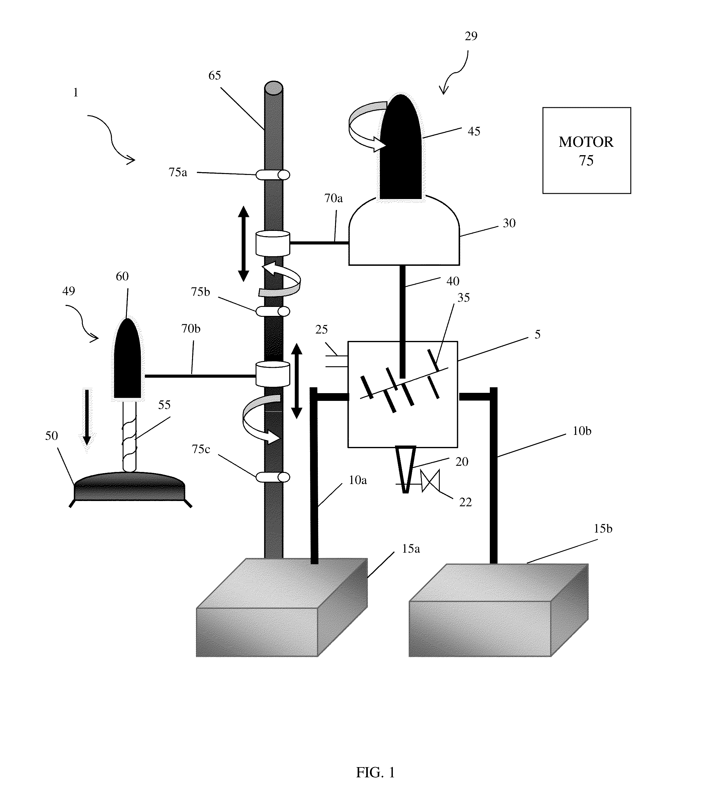
The invention relates to a batch mixer and, more particularly, to a batch mixer equipped with a plunger for pushing material from the batch mixer. Several techniques are available to process polymers, including twin screw extruders and batch mixers. Batch mixers provide for increased residence time of polymeric materials, which improves shearing history of the polymeric materials. Batch mixers, such as a Banbury® mixer, are known in the art of mixing polymeric materials. These batch mixers have several shortcomings, however. For example, in known batch mixers, after blending or mixing of the material is complete, the mixers are opened and the polymeric materials are manually scooped out from the mixer. This is done with the material in a molten state. This process is time consuming, expensive and complicated. When the polymeric material is solidified as a molten chunk, the polymeric material may be put in a crusher to form polymer granules. However, this form of materials cannot be pelletized. Accordingly, there exists a need in the art to overcome the deficiencies and limitations described hereinabove. In a first aspect of the invention, a batch mixer comprises a mixer tank structured to accommodate material. The mixer further comprises a mixer head comprising at least one blade structured to blend the material within the mixer tank. The mixer further comprises a plunger mechanism structured to push the blended material directly from the mixer tank. In another aspect of the invention, a batch mixer comprises a mixer tank having an interior portion structured to accommodate polymeric material. The mixer further comprises a mixer structured to blend the polymeric material within the interior portion of the mixer tank. The mixer is rotatable and moveable in a vertical direction along a shaft. The mixer further comprises a plunger mechanism structured to push the blended polymeric material through a die in fluid communication with the interior portion of the mixer tank. The plunger mechanism is rotatable and moveable in the vertical direction along the shaft. The mixer further comprises a plurality of limiters structured to limit the vertical movement of the plunger mechanism and the mixer. In yet another aspect of the invention, a method of mixing material comprises: placing material within a tank; placing a mixing head on the tank, and mixing the material within the tank with the mixing head; removing the mixing head from the tank; placing a plunger mechanism on the tank; moving the plunger mechanism within the tank to push the mixed material from a die; and removing the plunger mechanism from the tank. The present invention is described in the detailed description which follows, in reference to the noted plurality of drawings by way of non-limiting examples of exemplary embodiments of the present invention. The invention relates to a batch mixer and, more particularly, to a batch mixer equipped with a plunger for pushing material from the batch mixer. More specifically, in embodiments, the batch mixer includes a plunger mechanism to push material through a die of a mixer tank. Advantageously, the present invention provides for semi-continuous operation while controlling the residence time of a mixing and compounding process of, e.g., polymeric materials. Accordingly, polymeric materials may be easily and efficiently discharged from the batch mixer and fabricated into desired pellet shapes. As such, the present invention provides for a more cost-effective removal of polymeric materials from the batch mixer. In the area of polymer processing, mixing and blending, whether in solution or molten form, of different polymers with each other and blending them with organic and/or inorganic fillers and additives is important. The quality of mixing, blending, and compounding of polymeric materials, e.g., plastics, determines the properties of the final product. The benefit of using batch mixers over conventional systems, e.g., twin screw extruders, is that the residence time is higher in batch mixers such that shearing history of the polymeric material is considerably improved. Advantageously, the batch mixer of the present invention is capable of pushing material, e.g., polymeric material or food products, from the batch mixer, using a plunger mechanism. This avoids the shortcomings of known mixers, which require the user to open the mixer and manually scoop out the material, e.g., polymeric material, from the mixer, in a molten state (which is a time consuming and costly process). Thus, compared to conventional systems, in the batch mixer of the present invention, processed material, e.g., polymeric material or food products, may be easily and efficiently drawn out of the mixer and fabricated to a desired shape using a plunger and die system. Also, advantageously, the material exiting from the die may automatically be guided through a water bath to a pellitizer to obtain material in pellet form. The batch mixer is also equipped with an opening to introduce inert or purging gas into the batch mixer and/or to suck air out of the batch mixer, thus allowing the batch mixer to operate under vacuum. In embodiments, the material may be related to the research and development of food products. Many food products undergo a mixing process in order to achieve characteristics such as texture, homogeneity, composition and temperature. In embodiments, food mixing can include nano-emulsions, large particle suspensions, highly viscous pastes, or dry powders, with or without the incorporation of gas. In embodiments, the mixing may be: solid-solid mixing, such as powders or textural effects; liquid-solid mixing, such as butters, pastes and dough; liquid-liquid mixing, such as emulsions, margarines, and spreads; or gas-liquid mixing, such as fermentation or chlorination. Accordingly, mixing and blending of food products with additives, flavorings, texture, and other fillers is provided herein. In embodiments, the production of food pellets and flakes such as cereals, pastas, and candies require longer mixing times. As such, the present invention may be of great help to food research and development and food product mixing. The mixer tank 5 also includes a die 20 in fluid communication with the interior portion. The die 20 is structured to discharge materials from the interior portion of the mixer tank 5, as discussed below. A valve 22 is provided for controlling the flow rate of the material being discharged through the die 20. In embodiments, the die 20 can be customized to any desired shape such as a slit, annular, etc. In embodiments, the mixer tank 5 further includes an opening 25 (e.g., pipe in fluid communication with an interior of the mixer tank) which can be used to introduce an inert or purging gas into the mixer tank 5 to prevent undesired chemical reactions from taking place within the mixer tank 5. In alternate embodiments, the opening 25 is used to remove air or other gases from the mixer tank 5, thus creating a vacuum. As further shown in Still referring to In embodiments, the mixer head 29 and plunger head 49 are rotatably attached to a shaft 65 using an arm 70 More specifically, the pins 75 As thus should now be understood, a method of mixing and blending material, e.g., polymeric material and/or food products, can be achieved with the batch mixer of the present invention. For example, material is placed within the mixer tank 5, and the mixing head 29 is placed on the mixer tank 5. The mixing head 29 is activated, and more specifically, the one or more mixer blades begin to mix the material within the mixing tank 5. Once a desired residence time is achieved, the mixing head 29 is removed from the mixing tank 5. For example, the mixing head 29 can be lifted in a vertical direction, and rotated away from the mixing tank. The mixing head 29 can be locked into place by a pin or other equivalent locking mechanism. Thereafter, the plunger head 49 is placed on the mixing tank, by moving it in the vertical direction and rotating it to align with the mixing tank 5. The plunger mechanism, e.g., screw plunger, is activated in order to discharge the mixed material from the die 20. The valve 22 can be adjusted in order to adjust the flow rate of the mixed material. The plunger mechanism can then be removed from the mixing tank 5. The foregoing examples have been provided for the purpose of explanation and should not be construed as limiting the present invention. While the present invention has been described with reference to an exemplary embodiment, changes may be made, within the purview of the appended claims, without departing from the scope and spirit of the present invention in its aspects. Also, although the present invention has been described herein with reference to particular materials and embodiments, the present invention is not intended to be limited to the particulars disclosed herein; rather, the present invention extends to all functionally equivalent structures, methods and uses, such as are within the scope of the appended claims. A batch mixer is equipped with a plunger for pushing material from the batch mixer. The batch mixer includes a mixer tank structured to accommodate material. The mixer further includes a mixer head comprising at least one blade structured to blend the material within the mixer tank. The mixer further includes a plunger mechanism structured to push the blended material directly from the mixer tank. 1. A method of mixing material, comprising:
placing material within a tank; placing a mixing head on the tank, and mixing the material within the tank with the mixing head; removing the mixing head from the tank; placing a plunger mechanism on the tank; moving the plunger mechanism within the tank to push the mixed material from a die; and removing the plunger mechanism from the tank. 2. The method of 3. The method of solid-solid mixing; liquid-solid mixing; liquid-liquid mixing; and gas-liquid mixing. 4. The method of 5. The method of 6. The method of 7. The method of 8. The method of 9. The method of 10. The method of 11. The method of 12. The method of 13. The method of 14. The method of 15. The method of FIELD OF THE INVENTION
BACKGROUND OF THE INVENTION
SUMMARY OF THE INVENTION
BRIEF DESCRIPTION OF THE DRAWINGS
DETAILED DESCRIPTION OF THE INVENTION